
And now I’m going to finish this pedal build. Huzzah!
But before I do that I’ll share my method for mounting the LED.
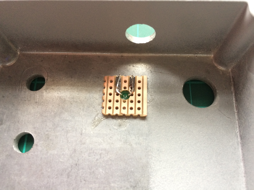
I don’t like LED bezels and prefer to have the LED poking through a 3mm hole in the enclosure. I found a useful method to achieve this in a forum post over at diystompboxes.com. It consists of a 5×5 hole piece of vero board with a hole drilled in the centre. I drill this hole just large enough so the LED can poke through it:

Then I glue this small piece of vero, track side facing outward, to the inside of the enclosure with the hole lining up with the LED hole.
The LED is pushed through the hole so it just pokes out the top of the enclosure. The LED legs are soldered to two vero tracks. Later on I can solder two connections from the main board and to the stomp switch to these tracks. Handy.
I suppose I could hot glue the LED into the hole but if I need to add a CLR I can solder it onto the mini-board here.
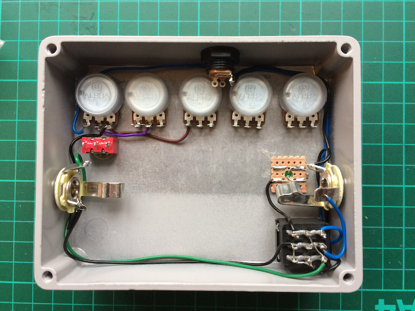
I then attach all of the pots, the DC socket, the mini switch, the stomp switch and the two jack sockets in the side:

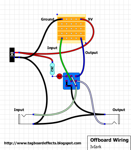
Then I start on the off-board wiring using the wiring layout found over on tagboardeffects:
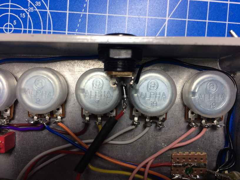
First off, I solder the connections between the pots, jacks and the stomp switch:
Then I add some polarity protection.
Here’s a Schottky diode soldered on the positive terminal of the SC socket. Wired in series, this protects against inadvertently powering up the pedal with the positive and negative terminals swapped.
I’ll put some heat-shrink over this to hide it:
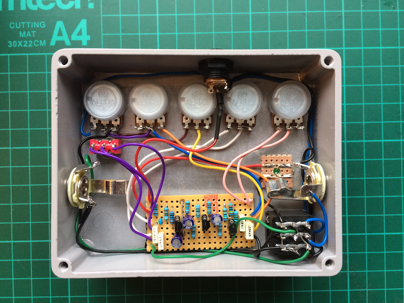
Here are all the connections completed. (It’s a bit mad that the circuit board is so tiny compared to all of the real estate taken up by the hardware)
And here it is!
Finished. 🙂

I need a beer…