
It’s time to solder the components to the vero board. This is the fun part. In fact, I think this is probably the easiest part of the whole process. 🙂
I like to add the shortest in height components first so that I build up the board from low to high. It makes it easier to fix the components to the board and my blob of blu-tack (“Barry”) likes it that way. So the usual order for soldering the components is:
– resistors
– diodes
– small ceramic capacitors
– sockets for integrated circuits and transistors
– polyester capacitors
– electrolytic capacitors
As this circuit doesn’t use any diodes we can miss out that stage (although later I’ll add a diode to protect against reverse polarity from the power supply but it will be off-board).
Resistors
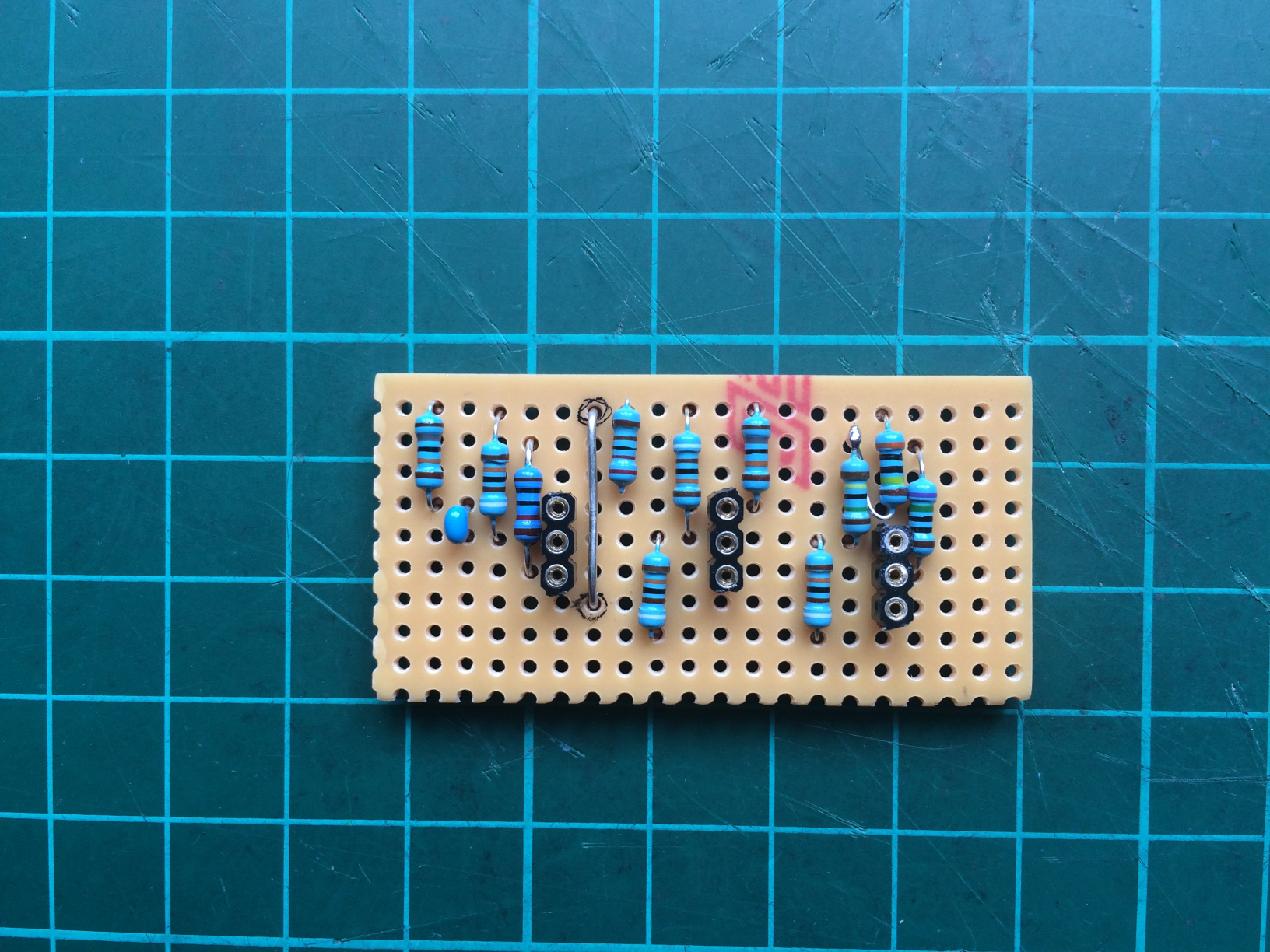
I solder on the resistors first working from left to right:
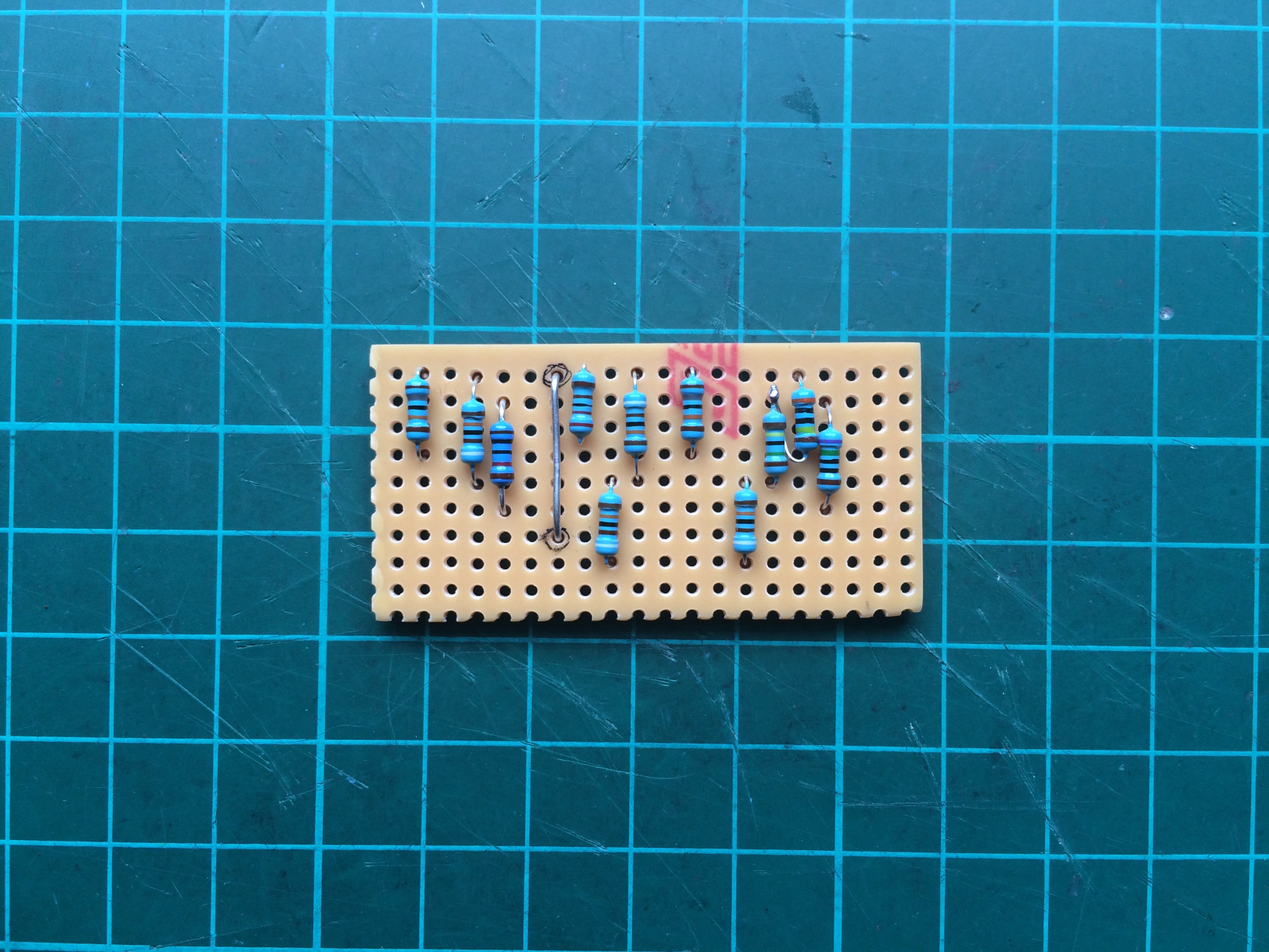
It’s worth double-checking the value of each resistor before soldering it. You can do this from the coloured bands if your eyesight is good or by checking the impedance on a multimeter. These ones are metal film resistors with a 1% tolerance so their values are pretty close to what they should be. You can use other types and tolerances like carbon film 5% tolerance, but these ones seem to be good quality and are cheap enough when bought in bulk.
Remember that I said I didn’t have a 4.7M ohm resistor? At the top-right you can see where I’ve soldered a 3M ohm resistor and a 1.5M ohm resistor together in series. I made a loop back from one of the leads of the resistors and soldered it to the lead of the other one. It looks a bit weird but it will do the trick since 3M ohm + 1.5M ohm = 4.5M ohm which is close enough.
Blu Tack
When I solder components I push their leads through the vero board holes and then flip the whole thing over using Barry the Blob of Blu-tack to hold the component in place and stick it to the desk:
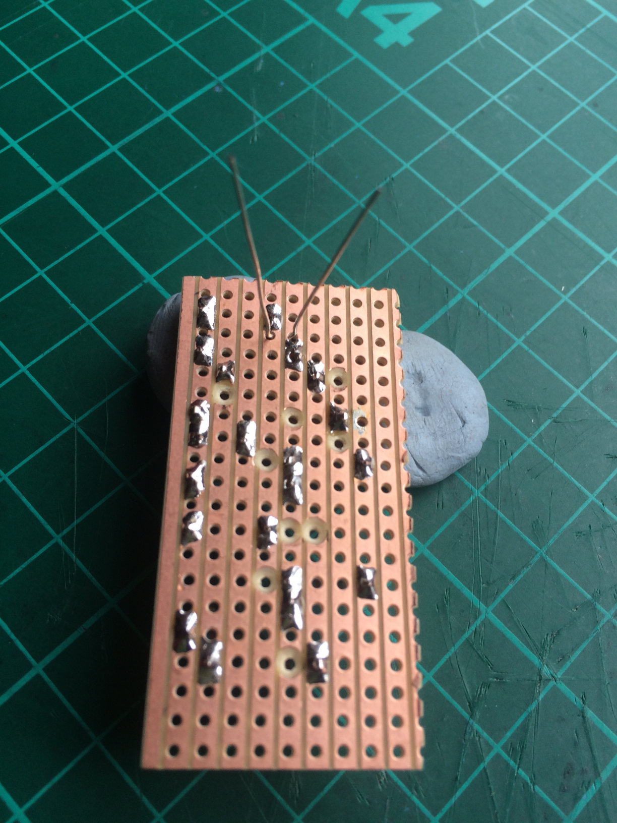
Once each lead of a component is soldered to the board I nip off any excess with some edge cutters and put the leads in a bag so I can re-use them for connections and jumpers on future projects (also, I’m as tight as Norbert Colon).
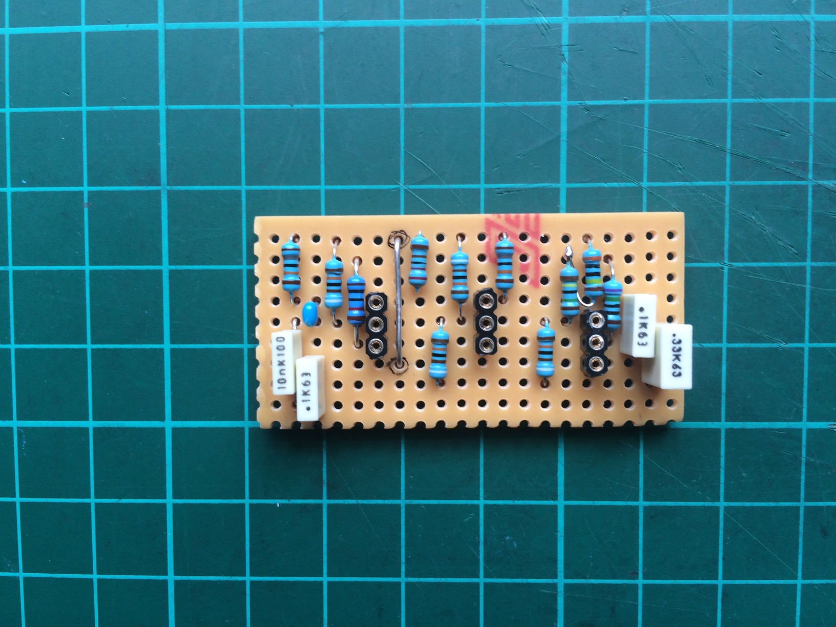
Small capacitor and transistor sockets
Now I’ll add the small ceramic capacitor and some sockets for the three transistors. I could solder the transistors directly to the board but there are two main reasons not to do that. Using a socket for these delicate components ensures that (1) the heat of the soldering iron doesn’t damage the transistor and (2) if I have a duff transistor, or put it in the wrong way around, or want to experiment with a different type, I can very easily swap these components out.
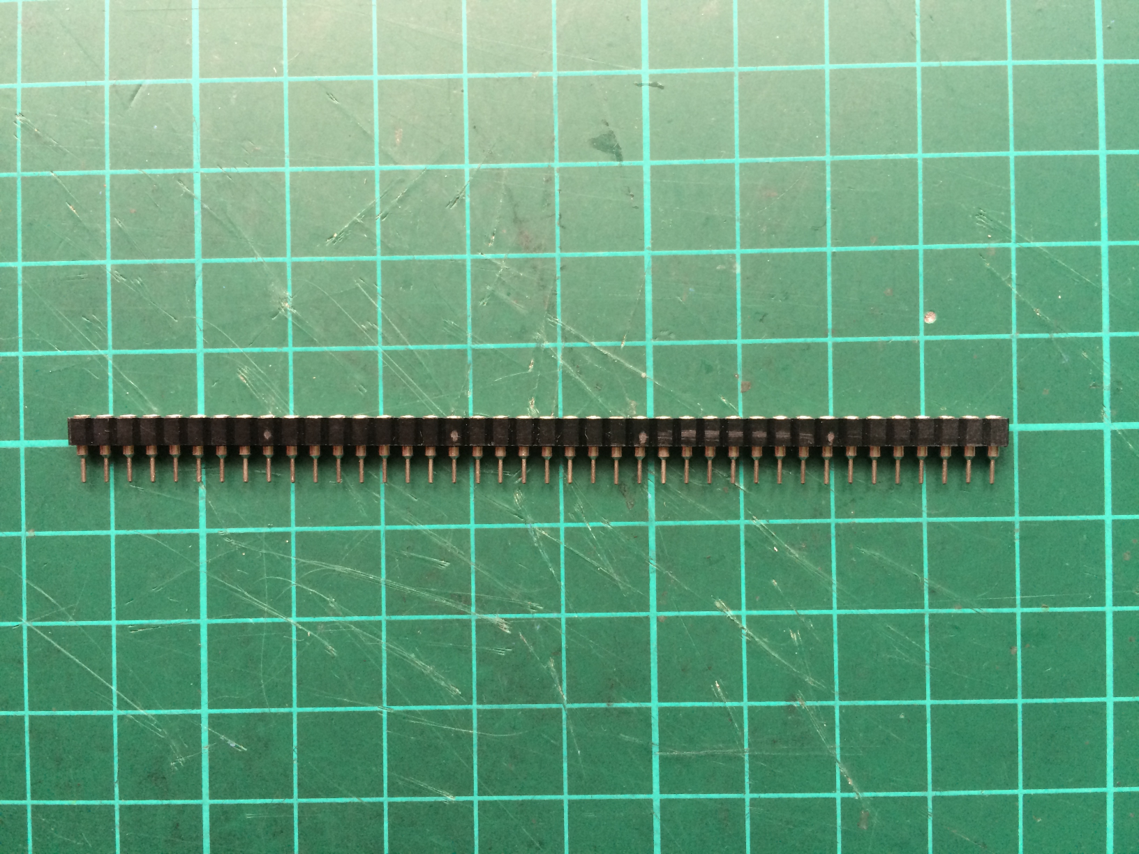
To make the three transistor sockets I bought a strip of “40 Pin DIP SIP IC Sockets Adaptor” from Tayda. It looks like this:
Using a Stanley knife I cut off three short lengths of three pins, one for each transistor:
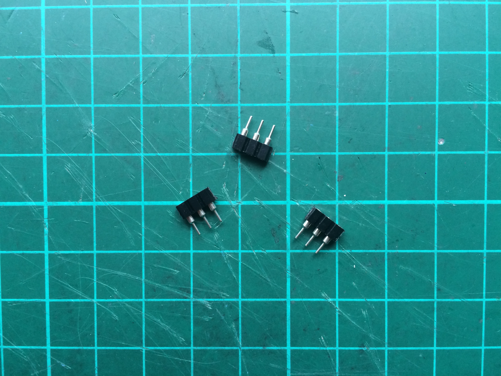
And, together with the small blue ceramic capacitor (it’s dinky, see if you can spot it), solder them to the board:
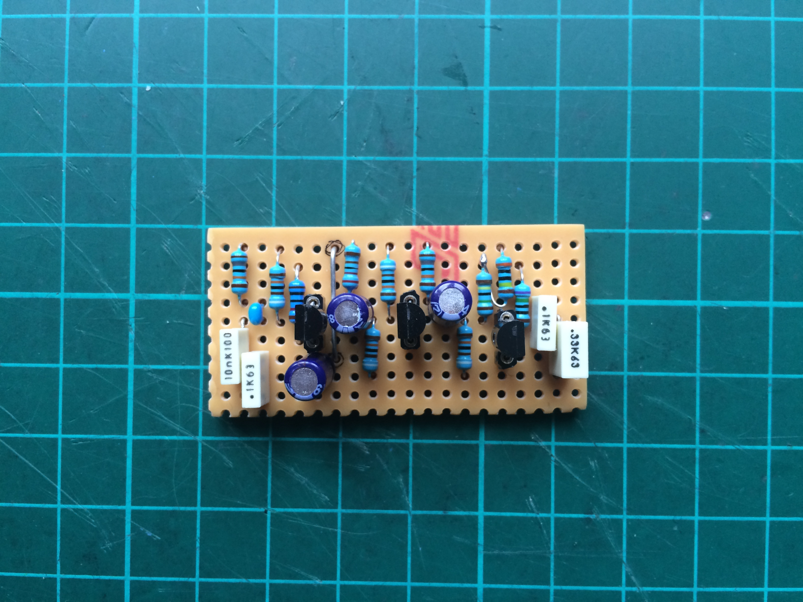
Next, I solder the four poly box capacitors to the board, bending their leads in some cases so that they span the required distance:
And then the three (blue) electrolytic capacitors (they remind me of tiny beer cans):

Be careful with electrolytic capacitors as they are polarised. They have a negative and a positive side so it’s very important to place them the right way around. Looking at the vero layout diagram you can see that they are represented by blue circles, and on one side of each blue circle there is a small white mark. In each case this small white mark is facing downwards. This is the negative side. The actual electrolytic capacitor will also have a white negative marking on its body and its lead will be shorter than the other one. If in doubt, check it out!
Final stages
Finally I push the transistors into their respective sockets.
The leads on these are too long so I snip them with my wire cutters and, making sure I have them the right way around, gently push them into their sockets:
And that’s it, all the components are now soldered to the vero board!
But before continuing to the next stage it’s worth double-checking all the solder joints to make sure there are no duff connections, or that you haven’t inadvertently welded a blob of solder across the copper tracks. Time spent inspecting your solder work now under a magnifying glass and a good light will be time well spent.
As this vero board will be sitting inside of an enclosure and on top of the backs of the potentiometers, height is an issue. If any of the components are too tall, you won’t be able to get the back of the enclosure on.
Here’s a side view of the board:
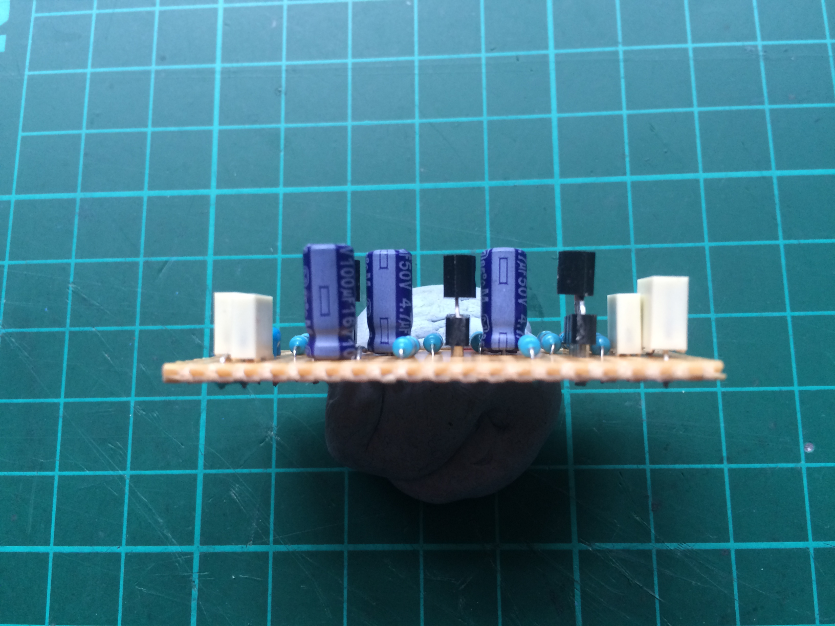
The tallest components are the electrolytic capacitors and the height of the whole edifice is about 13mm. That should be OK to allow enough clearance in the enclosure. We’ll find out if this is enough later on…