Building a Pedal Part 7

Right, let’s get on with this thing. I’m going to connect the vero board up to the test harness and see if this thing rocks. Or not…


Testing Board

As I said before, I’m not going to connect it to the actual pots and jacks that I’ll be using in an enclosure just yet. I have a testing breadboard that I can quickly connect everything to. Here it is:


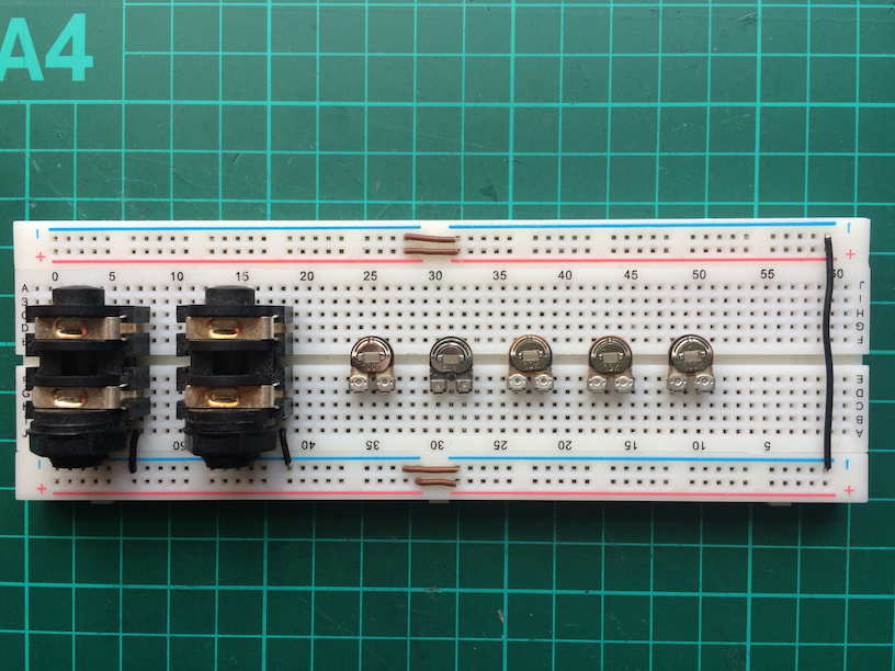
Starting from the left, there’s a jack socket for the guitar input, one for the guitar output and then 5 trim pots that are stand-ins for the 5 potentiometers that I’ll use later.

The jack sockets are attached to the breadboard and there are two small lengths of black wire connecting the ground terminals to the negative ground rail (the blue strip on the breadboard).

These sockets are 6.3mmm Mono Jack Sockets from Bitsbox

The trim pots are also from from Bitsbox. I bought a Trimmer Kit containing 45 of these pots with a range of values from 100R to 1M ohms. Very handy for prototyping.

From left to right the ones I’ve attached to the breadboard are:

– 100k (Density)
– 50K (Bias)
– 10K (Fuzz)
– 10K (Filter)
– 100K (Level)


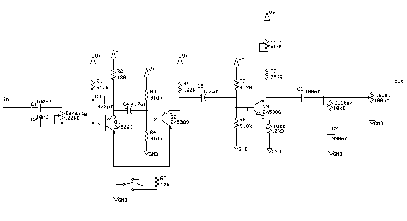
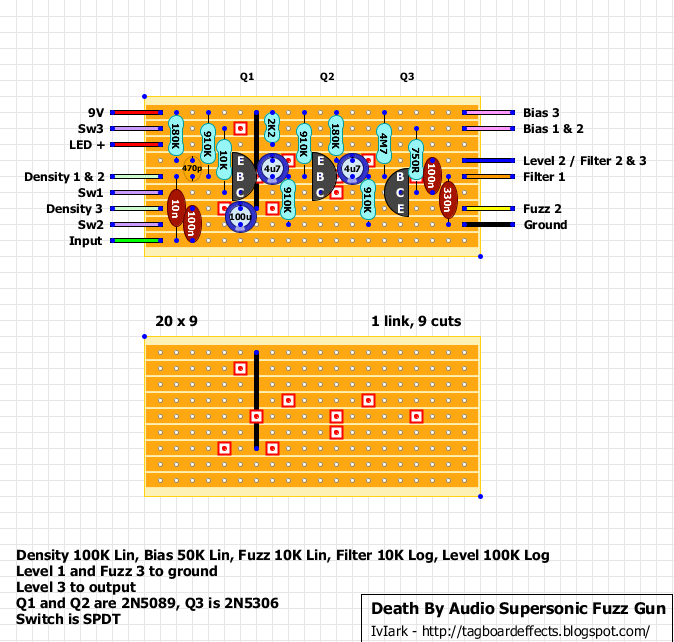
The rubric in the layout diagram specifies that some of the pots are Linear and some are Logarithmic:

“Density 100K Lin, Bias 50K Lin, Fuzz 10K Lin, Filter 10K Log, Level 100K Log”

These trim pots are all Linear but for testing it doesn’t matter. At this stage I just want to ensure that the circuit basically works. In fact, sometimes I use trim pots that are not the exact value specified but close enough.


Breadboard connections

Now I’ll refer to the layout diagram again to make the connections:


The first thing I do is see if there are any connections that I can make on the breadboard:

Density 1 & 2 – this wire will connect to the first two connections of the Density pot. So I can connect these two together on the breadboard.
Bias 1 & 2 – this wire will connect to the first two connections of the Bias pot. Again, I can connect these two together on the breadboard.
Level 2 / Filter 2 & 3 – this wire needs to connect to three places. I can connect all three with jumper wire on the breadboard.
Level 1 and Fuzz 3 to ground – this means that I can connect a short jumper wire from each of these to the breadboard’s negative ground rail.
Level 3 to output – this means I need to add a jumper wire from the third connection of the Level pot over to the output connection on the output jack socket.


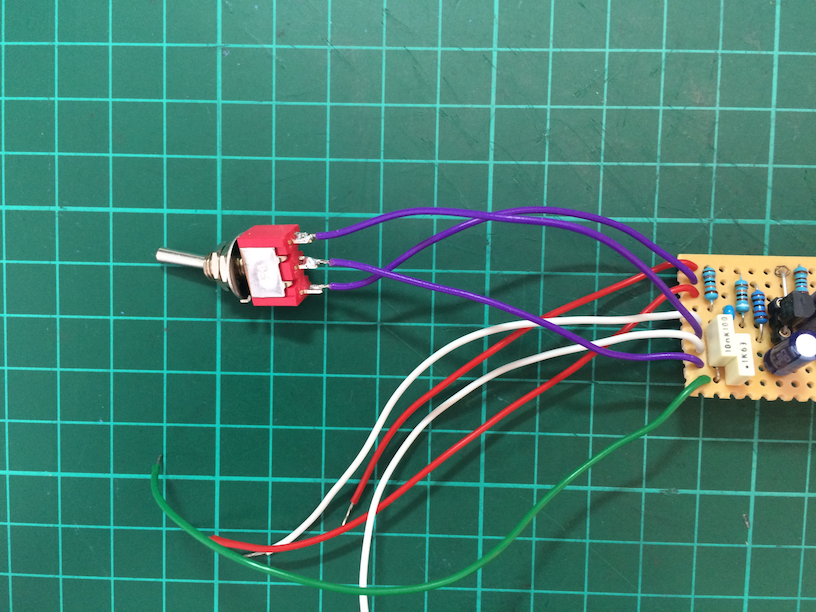
Here’s what those connections look like:


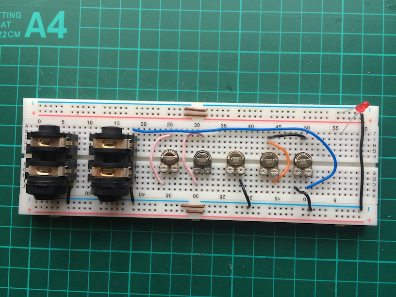
You can see the long blue jumper wire connecting from the Level pot to the output jack socket. Also, the two short black jumpers connecting to ground. Ignore the LED in the top-right as I just put it there to remind me to connect it up later.


Connecting the Vero Board

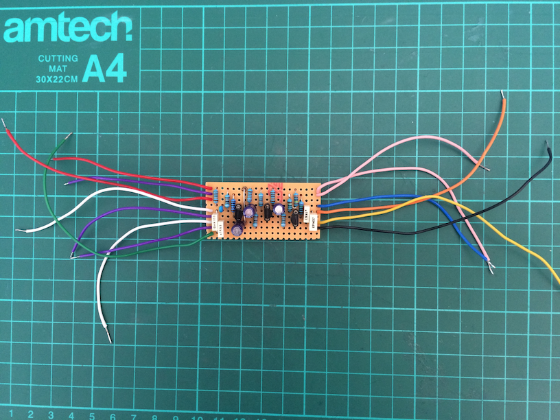
Now I’ll connect all the wires from the vero to the breadboard. Here’s a list of the connections as specified in the layout diagram, working from the top-left and then the top-right downwards:

9V – connects to the red power rail of the breadboard
Sw3 – (this wire is already soldered to the switch)
LED+ – connects to the positive side of the LED that I’ll add to the breadboard
Density 1 & 2 – connects to the Density pot terminal 1 or 2
Sw1 – (this wire is already soldered to the switch)
Density 3 – connects to the Density pot terminal 3
Sw2 – (this wire is already soldered to the switch)
Input – connects to the Density pot terminal 1 or 2

Bias 3 – connects to the Bias pot terminal 3
Bias 1 & 2 – connects to the Bias pot terminal 1 or 2
Level 2 / Filter 2 & 3 – connects to either of the Level terminal 2 or Filter 2 or 3 terminals (since they’re all connected together)
Filter 1 – connects to the Filter pot terminal 1
Fuzz 2 – connects to the Fuzz pot terminal 2
Ground – connects to the black power rail of the breadboard


And here it is connected up:


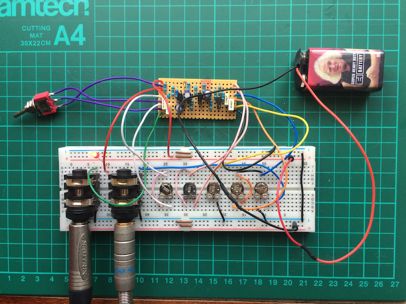
Note that I’ve connected the 3mm red LED between the negative ground rail and the connection coming from the vero board.

I’ve connected a 9v battery (courtesy of Electro-Harmonix) to the breadboard’s power rails and I’ve also plugged in a guitar and an amp. 🙂

And I’m ready to rock….and I’m hitting a power chord on my Strat…

….does it work?

Tune into tomorrow’s thrilling episode to find out!

Building a Pedal Part 6

Now to solder the connecting wires to the vero board. These wires will connect to the power supply, input and output jacks, the stomp switch, and the potentiometers (pots).

I need to refer to the vero layout so I’ll post it here again:


Wire

There are 14 wires to cut and solder to the board.

These layouts tend to stick to a colour scheme of red for 9V+, black for ground, green for input, and blue for output. Then various colours are used to connect to the pots and switches (if any). You don’t have to slavishly use the colour scheme but it helps to be consistent. For example, “Density 1 & 2” and “Density 3” look like some sort of light green wire, which I don’t have, so I’m going to use white wire for those.

In my first pedal builds I used single-core 0.6mm wire (I think this is 22AWG in American gauge) for these connections. You can get this from Bitsbox here or from other suppliers in bulk.


The nice thing about single-core wire is that it’s quite rigid and you can bend it inside the enclosure so it’s all neatly tucked away. However, as I found out the hard way, it’s also prone to break if you flex it at all. When I was manipulating the wires and routing them inside the enclosure some of the wires snapped off the board and I had to resolder them.

So now I use 7/0.2mm multi-stranded wire which you can also get from Bitsbox here or, as I prefer, in multipacks from Rapid here

“7/0.2mm” means that the wire consists of 7 strands of 0.2mm each. These strands ensure that you can bend and flex this stuff all day long and it won’t break. Having said that, I do still use single-core wire for the connections in the enclosure between the jack sockets, the DC socket, and the stomp switch. More on that later.


Cutters

I need to cut 14 shortish lengths of coloured mult-strand wire and strip a few mm off each end. I used to use a scalpel and my teeth to do this until I got fed up with that and bought myself some of these:


These strippers work really well and save me a lot of time. They’re a bit pricey, but good quality. Amazon have them here  though you might find them cheaper elsewhere.


Stripping, Tinning, and Soldering

Here are the wires, cut and stripped (well, some of them are stripped. I was a bit premature when taking this pic):


Now I’ll “tin” the ends of the wires with solder so that it will be easier to solder them to the board and to the various pots and switches. Luckily, Barry the Blob of Blu-tack is on hand to help out:


Then I solder each wire to the board, with Barry’s assistance:


And here they are, all soldered to the board:


Now all I need do is connect everything up in the enclosure and we’re good to go, right? Well, I could do that but if there’s something wrong like a faulty component or bad solder joint then it’ll be hard to find. I have a breadboard that I use as a kind of testing bed harness thing, and I’ll connect the vero’s wires to that for testing before soldering everything up. But before I do that I do want to solder one of the hardware items to three of the wires. This will make things a bit easier, as we’ll see later.


SPDT Switch

According to the layout diagram, the three purple wires should be connected to “Sw1”, “Sw2” and “Sw3”. This refers to the “SPDT” switch mentioned in the layout’s rubric. This stands for “Single Pole, Double Throw” which basically means that a single row of connections are connected in two positions. In one position, Sw1 and Sw2 will be connected, and in the other position, Sw2 and Sw3 will be connected. You can see this at the bottom of the schematic where the middle position connects to ground:

This switch needs to be of the mini toggle “On-On” variety.

You can also get “On-Off-On” types. These have a third, middle, position where none of the switch’s terminals are connected. But for this circuit we don’t need that.

Tayda do good prices on these mini toggles here.

So, I’ll solder this on to the three purple wires like so:


That’s enough for now. I’m going outside to look at that big orange glowing ball in the sky…

Building a Pedal Part 5

It’s time to solder the components to the vero board. This is the fun part. In fact, I think this is probably the easiest part of the whole process. 🙂

I like to add the shortest in height components first so that I build up the board from low to high. It makes it easier to fix the components to the board and my blob of blu-tack (“Barry”) likes it that way. So the usual order for soldering the components is:

– resistors
– diodes
– small ceramic capacitors
– sockets for integrated circuits and transistors
– polyester capacitors
– electrolytic capacitors

As this circuit doesn’t use any diodes we can miss out that stage (although later I’ll add a diode to protect against reverse polarity from the power supply but it will be off-board).


Resistors

I solder on the resistors first working from left to right:

It’s worth double-checking the value of each resistor before soldering it. You can do this from the coloured bands if your eyesight is good or by checking the impedance on a multimeter. These ones are metal film resistors with a 1% tolerance so their values are pretty close to what they should be. You can use other types and tolerances like carbon film 5% tolerance, but these ones seem to be good quality and are cheap enough when bought in bulk.

Remember that I said I didn’t have a 4.7M ohm resistor? At the top-right you can see where I’ve soldered a 3M ohm resistor and a 1.5M ohm resistor together in series. I made a loop back from one of the leads of the resistors and soldered it to the lead of the other one. It looks a bit weird but it will do the trick since 3M ohm + 1.5M ohm = 4.5M ohm which is close enough.


Blu Tack

When I solder components I push their leads through the vero board holes and then flip the whole thing over using Barry the Blob of Blu-tack to hold the component in place and stick it to the desk:

Once each lead of a component is soldered to the board I nip off any excess with some edge cutters and put the leads in a bag so I can re-use them for connections and jumpers on future projects (also, I’m as tight as Norbert Colon).


Small capacitor and transistor sockets

Now I’ll add the small ceramic capacitor and some sockets for the three transistors. I could solder the transistors directly to the board but there are two main reasons not to do that. Using a socket for these delicate components ensures that (1) the heat of the soldering iron doesn’t damage the transistor and (2) if I have a duff transistor, or put it in the wrong way around, or want to experiment with a different type, I can very easily swap these components out.

To make the three transistor sockets I bought a strip of “40 Pin DIP SIP IC Sockets Adaptor” from Tayda. It looks like this:


Using a Stanley knife I cut off three short lengths of three pins, one for each transistor:


And, together with the small blue ceramic capacitor (it’s dinky, see if you can spot it), solder them to the board:


Next, I solder the four poly box capacitors to the board, bending their leads in some cases so that they span the required distance:


And then the three (blue) electrolytic capacitors (they remind me of tiny beer cans):


Be careful with electrolytic capacitors as they are polarised. They have a negative and a positive side so it’s very important to place them the right way around. Looking at the vero layout diagram you can see that they are represented by blue circles, and on one side of each blue circle there is a small white mark. In each case this small white mark is facing downwards. This is the negative side. The actual electrolytic capacitor will also have a white negative marking on its body and its lead will be shorter than the other one. If in doubt, check it out!


Final stages

Finally I push the transistors into their respective sockets.

The leads on these are too long so I snip them with my wire cutters and, making sure I have them the right way around, gently push them into their sockets:


And that’s it, all the components are now soldered to the vero board!

But before continuing to the next stage it’s worth double-checking all the solder joints to make sure there are no duff connections, or that you haven’t inadvertently welded a blob of solder across the copper tracks. Time spent inspecting your solder work now under a magnifying glass and a good light will be time well spent.

As this vero board will be sitting inside of an enclosure and on top of the backs of the potentiometers, height is an issue. If any of the components are too tall, you won’t be able to get the back of the enclosure on.

Here’s a side view of the board:


The tallest components are the electrolytic capacitors and the height of the whole edifice is about 13mm. That should be OK to allow enough clearance in the enclosure. We’ll find out if this is enough later on…

Building a Pedal Part 4

Now that the vero board is cut to size I need to make a few cuts in the copper tracks and solder in one wire connection as per the vero layout diagram above. The vero layout’s 2nd image shows what needs to be done:

The red squares represent 9 cuts in the copper tracks on the back-side of the vero board and the black line represents one wire connection on the front of the vero board.

Remember that this image shows the cuts as if you are looking from the non-copper side of the vero board (pretend that you have x-ray vision). This means that when you are actually making the cuts the board is flipped over horizontally and so you need to work with a mirror image of the cuts diagram. I use image editing software to create a flipped mirror image:

Now I work from this image and not the original one. Using a pen or pencil I mark on the vero board where the cuts will be:

The cuts are made using a 3mm drill bit, turning it clockwise just enough so that it creates a break in the copper track. Not too much pressure is needed. I bought one of these to make my life easier:

I twist and cut each one like so:

Here’s the finished job:

At this stage it’s a good idea to grab a multimeter and set it to continuity mode to make sure that the cuts are true, and that there are no fragments of copper that might still allow a connection across the tracks.

I now need to add one wire connection. This time the vero layout shows it correctly because the connection will be added to front of the vero board. It’s just a short piece of wire cut to the appropriate length. With a pen I mark the two holes on the front-side of the vero board:

(Notice my favourite tool – a big blob of blu-tack. I use this to hold the vero board in place when I’m working on it. Also I use it to hold the components in place when soldering).

I’ll bend the wire so it pokes through the two holes then solder it on the other side and snip off any excess wire with some cutters:

That’s enough for today. Next time I’ll solder the components onto the vero board.

Building a Pedal Part 3

And, as if by magic (or in the tradition of Blue Peter’s “here’s one I prepared earlier”), I have the components!

From the left there are 4 polyester box capacitors, a 470pF multilayer ceramic C0G capacitor, three electrolytic capacitors, the three transistors and, at the top, the resistors.

  • The four polyester box capacitors are from Bitsbox. These are generally a good size, not too tall and fit nicely on a veroboard
  • The 470pf multilayer ceramic C0G capacitor is from RS (link), I chose a “C0G” type (or “NP0”) because it has a better tolerance than plain ceramic, and less likely to be microphonic. Also, because the gurus on this forum advised me to use C0G/NP0 types for ceramics where possible
  • The three electrolytic capacitors are made by Panasonic and are from CPC. I chose to use a better quality rather then cheaper brands because I can. 😉 (Notice one of the caps has short stubby leads. I salvaged it from another project.)
  • The three transistors are from Tayda. I’m not sure about the quality of these so I’m not going to directly solder them onto the vero board, but will instead use sockets in case I need to swap them out.
  • Notice there are eleven resistors, not ten. The circuit uses a 4.7M ohm (“4M7”) resistor which I don’t have and I didn’t want to order a pack of 100. 😉 I do, however, have a 3M ohm resistor and a 1.5M ohm resistor so, using the magic of Ohm’s law I can combine them in series to give me 4.5M ohms, which is close enough. I’ll need to think about how to solder them together so it doesn’t look messy.

At this stage I’m not concerned with the SPDT switch, nor the pots. For now I just want to prepare the vero board and solder these components onto it.


Now I need to cut a piece of vero board to size. When I buy this stuff I get it in sizes of 24 tracks by 37 holes. The vero that’s used in the circuit is 9 tracks by 20 holes so I need to cut it to size with a Stanley knife.

TOP TIP – double check that you have the vero board the right way round. That is, you need 9 tracks going horizontally. A few times now I’ve cut it the wrong way round and ended up with the tracks going vertically. D’oh!

Here’s a piece of vero that I’m using from a previous cut. At the moment it’s 23 tracks by 20 holes. So I need to make another cut to reduce it to 9 tracks in height. I mark out a line on each side of the board with a pencil on the 10th row. It makes sense to cut through a row of holes:

Then, holding down a steel ruler with one hand acting as a guide, I make a series of scores with the Stanley knife with the other hand starting on the copper side, flip it over, and cut another series of scores on the other side:

I keep scoring it with the knife until I get a clean cut:

Be careful of the dust, it’s nasty stuff and you don’t want to breathe it in. Also, watch your fingers. What you can’t see in the last photo is a piece of my fingernail where the knife took out a nice chunk. 😉

Building a Pedal Part 2

I think it’s useful to have the schematic to cross reference and see the theory behind it all. After Googling “Death By Audio Supersonic Fuzz Gun Schematic” I found this:

And I’m going to order the parts. I can get most things from:

Bitsbox – a great place for audio components
CPC – good for general purpose stuff like resistors and capacitors
RS – like CPC, good for general stuff
Tayda – a really great and cheap company in Thailand – they do a 15% discount
code about twice a month – keep a lookout on their Facebook page.

But to be honest, I’ve already stocked up on some resistors and capacitors since it’s cheaper to buy in larger quantities.

Here’s my buying guide:

The only tricky component was the 2N5306 transistor which I couldn’t find at CPC, RS, or Bitsbox, but Tayda have some so I ordered a few, at the same time as stocking up on some more enclosures and knobs.


Here’s the plan:

  • Collect the various components
  • Cut and prepare the vero board
  • Make the first connections and add some components

I get the vero board from Bitsbox. I buy it in packs of 5 or so and it looks like this:

You can also get it on Amazon:


Begin typing your search term above and press enter to search. Press ESC to cancel.