
Yes, it works!
I connected the battery, the guitar and the amp, gently turned up the volume…. and was regaled with a loud siren-like oscillation. I was prepared for this, though, as the Supersonic Fuzz Gun is supposed to do that.
When I built a Fuzz Factory earlier this year a similar thing happened and I spent a long time re-checking all my solder connections looking for errors. Then I thought, “Wait. Go on Youtube and find out what this thing is supposed to sound like”. Yep, it was supposed to sound like a wailing banshee with certain settings. Same with the Fuzz Gun. Flipped the SPDT switch and it sounded relatively normal.
So I played around with it for a while, adjusting the trim pots with a screwdriver. Good fun.
I tried some experiments:
- 2N5088 transistors in place of the 2N5089s transistors sounded like a wet fart. There was no oscillation in that mode. Back to the 2N5089s!
- I disconnected the SPDT switch and connected a 10k pot (also tried a 5K pot) to the “Sw1” and “Sw2” connections. All the pot did was change the frequency of the oscillation and then turn it off past a certain point. As turning the “Density” pot already changed the frequency of the oscillation it doesn’t bring much to the party. So, back to the SPDT switch.
Enclosure
So now I need to think about what enclosure to use and the artwork.
A 1590B might be a bit tight for 5 pots and a switch, although I have built a Fuzz Factory with 5 pots but no switch. But a 1590B wouldn’t leave much real estate for artwork. I could use a larger 1590BB enclosure.
I spent a lot of time umming and ahhing about what size enclosure to use. I played around with placing 5 knobs and a stomp on a 1590B sized enclosure and, even though I could probably pack everything on, I don’t think there’d be much room left for artwork. So I decided to use a grey 159BB size enclosure (bought from Tayda).
Earlier today I spent some time thinking about the artwork with the theme being “supersonic” and “gun”, or “ray gun”. A Google search provided me with the solution which I found here. I then spent a lot of faffing around in the image editing software ensuring everything lined up.
Onward…
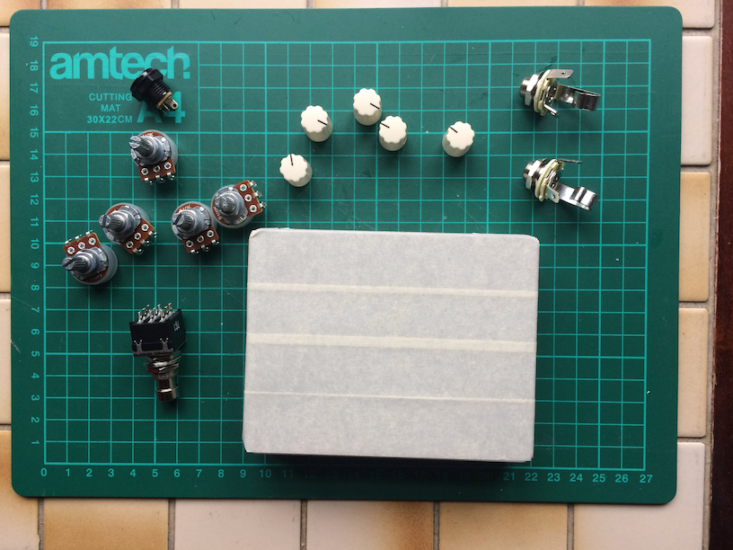
So now I gather all the pots and knobs and switches and wrap the enclosure in masking tape. This offers some protection from drill bits, metal shavings, and also means its easier to mark out the drill points:
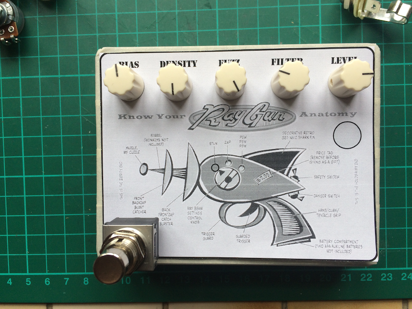
Then I print out the artwork on a black and white laser printer to check if everything lines up with the hardware. Some of the text doesn’t line up so I adjust that and try again:
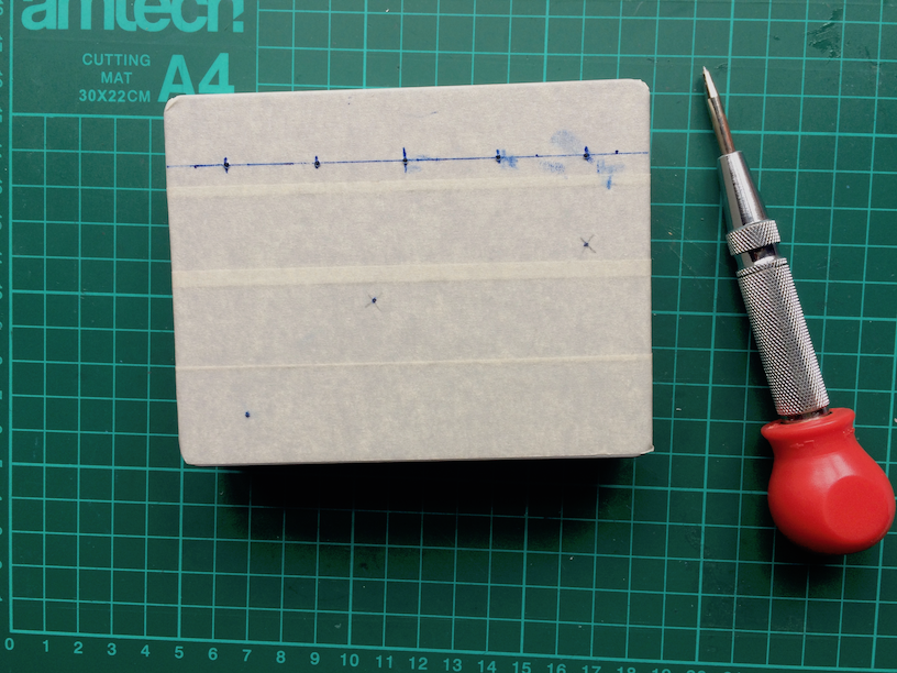
Now I measure where the holes are going to be for the pots, switches and sockets. I use a centre punch to mark these out:
Then I drill some 3mm guide holes and then use the stepper drill to drill out all the holes:
Mini-switch = 6mm
Pots = 7mm
Jack Sockets = 10mm
Stomp Switch = 12mm
DC Socket = 12mm
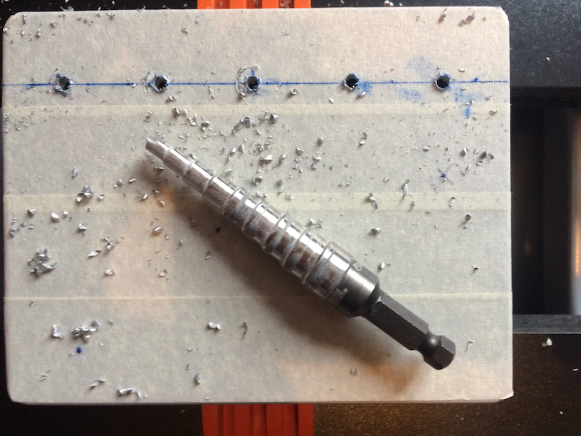
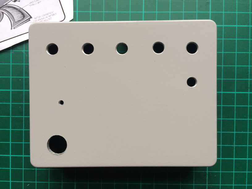
This is it drilled. Five holes across the top for the pots, then a hole for the mini-switch, a small hole for the LED and the big hole is for the stomp switch. You can’t see the holes for the DC socket or the jack sockets, as they are on the sides:
Here’s the artwork (not my handiwork, I found it on Google Image Search) printed on glossy sticky paper:

And then I stick it onto the enclosure and cut out the holes with an X-acto knife (the LED hole lines up with the end of the ray gun):
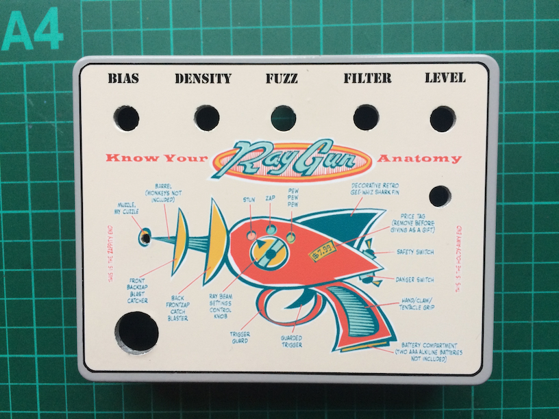
It’s not perfectly centred on the box, but sod it, it’s close enough.
Now I’ll put it to one side and get ready for the Envirotex stage.